


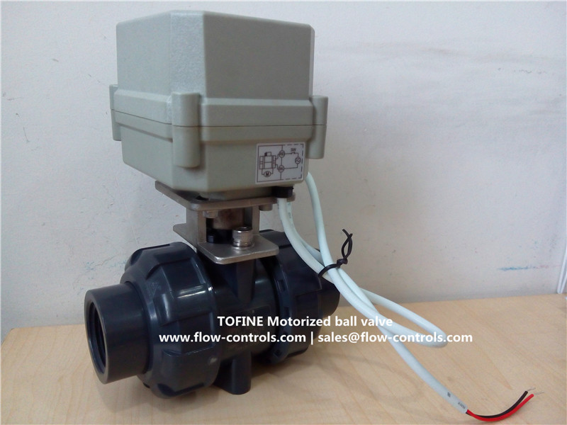
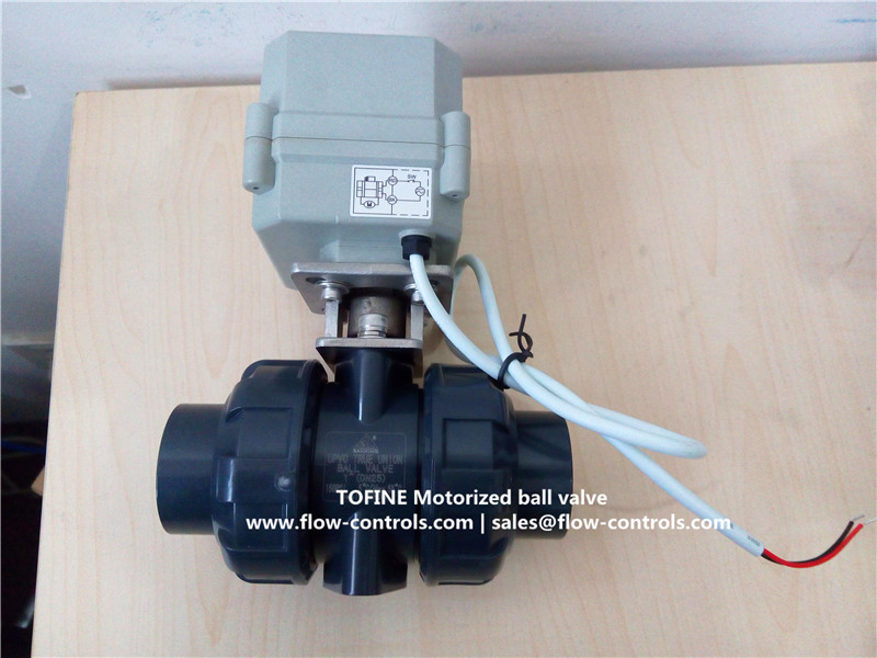
Electric&Motorized ball valve in PVC

Product Name:
Electric&Motorized ball valve in PVC
Product Abstract:

- Product Description
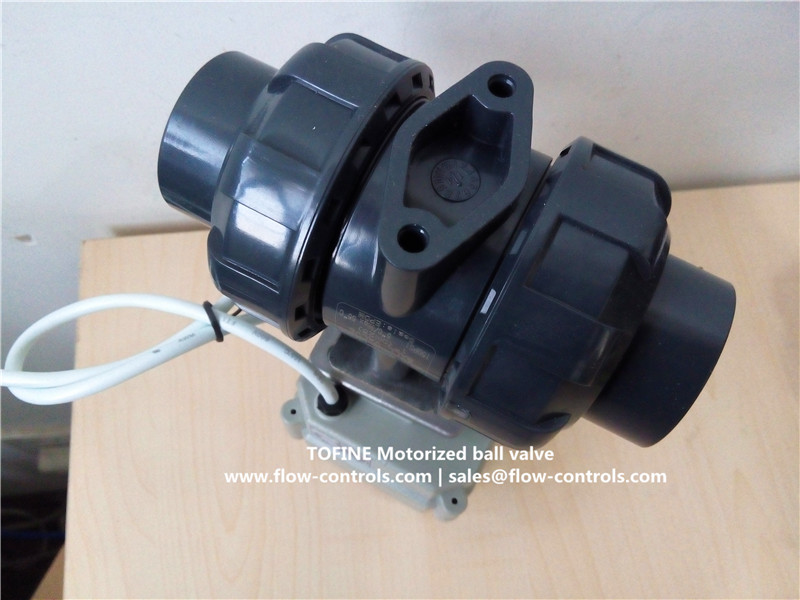
TOFINE motorized ball valve in PVC,2-way TOFINE Electric PVC ball valve in China,
Size:1/2" (DN15),3/4"(DN20),1"(DN25),Below pictures are for 1"PVC motorized ball valves ,
Technical Parameters:
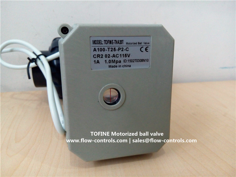
Product size NPT/BSP 1/2", NPT/BSP 3/4", NPT/BSP 1" (Optional) Maximum working pressure 1.0MPa Circulation medium Fluid, Air Rated voltage DC12V, DC24, AC/DC9-35V, AC110-230V(Optional) Wiring control methods CR2-01, CR2-02 , CR3-03, CR4-01, CR5-01,
CR5-02, CR7-03, CR7-04 (Optional)
Working current ≤ 800MA Open/close time ≤ 15 Sec Life time 70000 times Valve Body material PVC Actuator material Engineering Plastics Sealing material EPDM & PTFE Actuator rotation 90° Max. torque force 10 Nm Cable Length 0.5m,1.5m (Optional) Environment temperature -15℃~50℃ Liquid temperature 2℃~90℃ Manual override NO Indicator Yes Protection class IP67 


You see,the size is not fully full port size,the details is listed below:
1/2" actual internal size is 13mm,
3/4" actual internal size is 18mm,
1" actual internal size is 23mm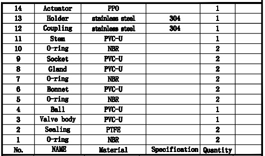
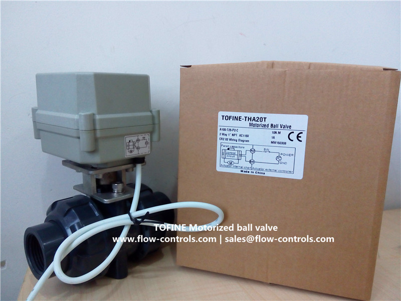
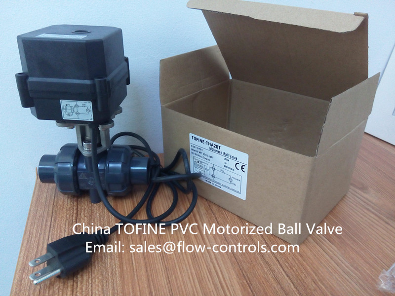
The default color of actuator housing is Grey,if you want Black color actuator housing we can also provide you,below picture for example:
Multiple wiring diagram available now:
CR2 01 Wiring Diagram ( 2 wires control )Wiring diagram
·RD connect with positive, the BK connect with negative, the valve closed, the actuator automatically power off after in place , the valve remains fully closed position
·BK connect with positive, the RD connect with negative, the valve open, the actuator automatically power off after in place, the valve remains fully open position .
﹡Suitable Working Voltage: DC5V/DC12V/DC24V﹡Exceeding the working voltage is forbidden
CR2 02 Wiring Diagram ( 2 wires control – Spring return in case of the power failure)

·When SW is closed , the valve open. the actuator automatically power off after in place
·When SW is open, the valve closed, the actuator automatically power off after in place
﹡Suitable Working Voltage: AC/DC9-35V﹡Exceeding the working voltage is forbidden
CR3 03 Wiring Diagram (3 wires control)

·RD& GR connect with positive, the BK connect with negative。
·SW CLOSED, the valve OPEN, the actuator automatically power off after in place
·SW OPEN, the valve CLOSED, the actuator automatically power off after in place.
﹡Suitable Working Voltage: AC/DC9-35V/AC110-230V
﹡Exceeding the working voltage is forbidden
CR5 01 Wiring diagram ( with feedback signal)
1RD connect with positive, the BK connect with negative,the valve closed, the actuator automatically power off after in place .

2 BK connect with positive, the RD connect with negative,the valve open, the actuator automatically power off after in place .
3.BL & WT are connect when the valve open fully, YW & WT are connect when the valve closed fully
Suitable Working Voltage::DC12V,DC24V
Exceeding the working voltage is forbidden
CR502 Wiring Diagram ( 5 wires control – Spring return)

·When SW is closed , the valve open. the actuator automatically power off after in place
·When SW is open, the valve closed, the actuator automatically power off after in place BL & WT are connect when the valve open fully, YW & WT are connect when the valve cl osed fully
﹡Suitable Working Voltage: AC/DC9-24V,AC/DC110V-230V,
﹡Exceeding the working voltage is forbidden
CR7 03 Wiring Diagram ( 7 wires control with feedback signal )

·RD& GR connect with positive, the BK connect with negative。
·SW CLOSED, the valve OPEN, the actuator automatically power off after in place
·SW OPEN, the valve CLOSED, the actuator automatically power off after in place.
·BL & GY connect with the valve’s fully open signal wiring
·YW & WT connect with the valve’s fully closed signal wiring.
﹡Suitable Working Voltage: DC12V,DC24V
﹡Exceeding the working voltage is forbidden
CR7 04 Wiring Diagram ( 7 wires control with feedback signal )

·RD & BK are connected to the power, WT & YW are connected to the controlled wiring.
·When the SW is closed , the valve open
·When the SW is open , the valve closed
·BL & GY connect with the valve’s fully open signal wiring
·YW & WT connect with the valve’s fully closed signal wiring.
Suitable Working Voltage::AC/DC110V-230V
Exceeding the working voltage is forbidden
If any questions please contact us via Email: sales@flow-controls.com, Web: www.flow-controls.com
- Related Products
- [Return Home] [Print] [Go Back]
